
Warning! According to the law gas boilers are falling under ‘controlled service’ appliance. Use only qualified specialist to work on your Alpha Innovation Boiler (GasSafe registered technician).
In an Emergency
When you suspect water or gas leak turn off the electrical supply and turn gas supply at the meter immidiately. open the windows to let the fresh air and call your customer support immediately and request service boiler technician as soon as possible.
Before using the boiler, after each restart and repair following steps should be taken
- electrical supply (should be 230V) and electrical safety checks (check correct electrical polarity,test short circuit, earth resistance test and earth continuity)
- gas supply checks (correct gas supply provided and that it is purged, inlet gas pressure of minimum 20 mbar needed- at the gas valve point)
- start boiler to verify correct operation of its control system
- examine water system connections and fittings, verify if the system pressure is set at the right levels, where not refill, vent and re-check the system
- examine all ventilation openings, those need to be right size and its opening needs to be clear
Servicing your Appliance
For safety and economy reasons it is advised that your boiler should be serviced once per year. Proper ventilation should be checked periodically. Standard 230V ~ 50Hz electricity supply is required for all Alpha Innovation boilers. Never hang flammable items over the boiler, never block ventilation channels. The boiler does not require any special air vents for cooling purposes located in the room in which it is installed or when installed in a cupboard or compartment. However minimum clearances must be kept for servicing purposes.
Attention! A cupboard or compartment used to enclose the boiler must be designed and constructed specifically for the purpose,i.e. comply with the Building Regulations.
All Alpha innovation boilers aren’t suitable for external installation. Your model needs to be installed on a flat vertical wall which is capable of supporting the weight of the boiler. The boiler can be fitted to or adjacent to a wall comprising of a combustible material without the need for a special thermal insulation barrier. The Alpha Innovation boilers can be installed in any room or internal space when following IEE Wiring (BS7671) Regulations. Also most of the boilers are capable of fitting into a cupboard or compartment. Cupboards and compartments should be designed for boiler storage purpose and comply with the Building Regulations & Requirements.
Basic technical requirement of boiler system for providing hot water:
- min. flow rate needed for the flow switch and burner to operate- 2.0 litres/min
- incoming mains water pressure-between 0.2 and 8 bar (for efficient operation). Where water pressure at mains exceeds 7 bar a pressure reducing valve should be installed
- for economic use purpose the pipe running between the boiler and taps should be 15 mm copper pipe and as short as possible
- all taps used at home as well as all mixing valves that are used for the hot water system should be able to operate at a mains pressure of up to 8 bar
- for bidets usage no anti-syphonage are required, provided the outlets are shrouded and it is not possible to attach a temporary hand held spray. A supply of direct mains fed hot and cold water is permitted provided the appliance is of the over-rim flushing type.
- the mains water supply connection to the boiler must be the first connection from the mains supply.
Fault finding
All Alpha Innovation boilers are equipped with indicator A and B neons. Indicator neons should be used for basic fault finding
Table 1. General fault finding based on neons signalization
| Problem | Error | Solution |
| ‘B’ alternating ‘A’ continuous |
pump fault or primary flow restricted | 1. Check gas supply and rectify fault 2. Replace pump |
| ‘A” ‘B’ alternating | CH system pressure to low | Re-pressure to 1,0 bar |
| ‘A” ‘B’ alternating | blocked flue or fan fault | 1. Check the pump 2. Replace fan |
| B’ alternating | primary/DHW temperature sensor fault | Replace primary/DHW temperature sensor |
| B alternating every 5 seconds | boiler not switched on | Electricity supply to the boiler is off |
| ‘A” ‘B’ alternating at the same time | fan fault | Replace fan |
| A’ continuous | selector switch fault | Reset the boiler |
| A’ alternating | overheat thermostat fault | 1. Reset the boiler 2. Replace overheat thermostat if necessary |
Table 2. General fault finding based on experienced problems
| Problem | Error | Solution |
| Burner fails after 10 secs | burner fault | 1. Reset the boiler 2. Replace burner if necessary |
| Burner output doesn’t modulates to maintain temperature set at a thermostat | gas valve adjustment fault | 1. Reset the boiler 2. Reduce DHW flow rate |
| DHW swicth senses no flow | DHW flow switch fault | Replace DHW switch sensor |
| Pump jammed | pump fault or primarly flow resticted | Replace pump |
| PCB not reacting | PCB fault | Replace PCB |
| Heating works but no hot water | DHW sensor fault | Replace DHW sensor |
| No heating, no hot water | primarly temperature sensor fault | 1. Replace primarly temperature sensor fault 2. Replace DHW sensor |
| No gas at a burner | no flue fault | Ensure gas is on and purged |
| No gas at a burner | gas valve fault | 1. Adjust gas valve 2. Replace gas valve |
| No gas at a burner | PCB fault | Replace PCB |
| Spark generator making a clicking noice | PCB fault | Replace PCB |
| No continuity across thermostat terminals | overheat thermostat fault | Replace overheat thermostat |
| Vent air, clear blockage | pump fault or primarly flow resticted | Replace pump |
Table 3. General fault finding based on experienced problems CD18, CD24 & CD 50 models
| Problem | Solution |
| Boiler is not providing central heating or hot water. | 1.Check there is power to the boiler. 2.If not then contact your service company. |
| Boiler is not providing central heating or hot water but attempts to fire | 1.Reset your appliance, after this your boiler will try to repeat its ignition sequence. 2.Check gas supply ( you can try switching on i.e. cooker) – If not then contact your gas service company. |
| Boiler is not providing central heating or hot water | 1.Reset your appliance , then boiler should then re-light. If fault recurs this indicates an overheat condition. The boiler should be turned off and your installer contacted. 2. Replace primary temperature sensor fault 3. Replace DHW sensor |
| Boiler fires occasionally for approx. 3 minutes | 1.This is a normal function of the boiler to periodically pre- heat the plate heat exchanger to optimize delivery time for domestic hot water to taps or showers. |
| Burner does not stay alight | 1.Check and correct if pressure tubes are connected and not blocked 2. If ignition can be called a small explosion then check wiring to ignition generator 3. When problem persit contact your installer/service company. |
| Spark at ignition goes for 10 sec but no ignition | 1.Check ignition electrode and lead, replace if necessary 2.Check electrode connections and fix if necessary 3.Check and correct spark gas and possition 4.Check and correct connections at ignition generator and PCB 5.Check for blocked flue and fix if necessary 6.When problem persist contact your installer/service company. |
| Pump and fan doesn’t run | 1.Check and correct electrical connections 2.Check and correct restriction in flue 3.Check and replace fan if necesary 4.Check and replace PCB if necessary 5.When problem persist contact your installer/service company. |
| Neon D illuminates continously | 1.Check and replace PCB 2.Check and replace fuse 3.Check and replace wiring 4.Verify electrical supply 5.When problem persist contact your installer/service company. |
| Burner lights but neon C illuminated | 1. Check and correct if pressure tubes are connected and not blocked 2. If ignition can be called a small explosion then check wiring to ignition generator 3. When problem persit contact your installer/service company. |
Boiler operation
The boiler operating mode is controlled by the selector switch on the facia panel. When set to , the boiler will only operate in the Domestic Hot Water mode. When set to , it will operate in the Domestic Hot Water and Central Heating mode.
Attention: The clock (optional part) is capable of controlling central heating operation not hot water domestic system. DHW is capable of constantly controlling hot water domestic system. The whole boilers operation is designed to provide priority to domestic hot water supply over the central heating. If a demand for hot water is required during a central heating period, the boiler will automatically switch to the hot water mode until the demand is satisfied. This interruption in the central heating is only when the demand for hot water is present.
Central heating mode
Whenever a call for heat applicable, the pump will automatically start to circulate the water in the central heating system. At this time and when air pressure switch will light the burner, fan will start to run at its full speed. The burner is suppose to adjust to provide the system demand. At the point when the temperature of the water reaches the set temperature burner output will be reduced accordingly. The moment that demanded temperature is reached, burner will switch off. Normally fan would continue to run for 20-30 more seconds, and then minimum 3 minutes will pass bufore burner is allowed to re-light. Approximately 3 minute interval is used for reducing residual heat that boiler produced. Whenever the CH (central heating) sensor did not recognize the pre-set temperature, and the thermostat shows the right level the burner will be turned off. In this case fan will continue to run for about 20 seconds and then the pump will run for another 30-40 seconds. In those cases there is no 3 minute off interval before re-lighting the burner. Whenever the is a need for DHW (domestic hot water) during the 3 minute interval, the boiler will provide hot water till the tap is closed. After tap is closed the boiler will immediately change back to providing CH.
Attention: Too low system pressure will prevent the primary pressure and boiler itself from operating.
Domestic hot water mode
Whenever a need for hot water is demonstrated (i.e. hot tap opening) mains water that is coming through the bi-thermal heat exchanger is being recognized by the flow switch, the burner will light somewhere around its middle output, and raise from there very fast to its maximum output. Burner output is being set by temperature selected by user. Whenever the is no water flow recognized by the flow switch,burner will turn off and the boiler immediately goes back to the central heating mode.
In both cases the fan will operate at full speed before each burner re-light, fan will stay at that speed till the need is fullfilled. When the burner is turned off, the fan will continue to run for 20 seconds if the selector is set for hot water only.
Parts replacement
Warning! Before start to work on any Alpha Innovation boiler set the boiler into OFF position (move to gauge to off), close valve that supplies fuel and isolate the supply of electricity. Wait till the boiler cools down. Take a note of what fuel is suppose to be used (label on the inside of case side panel). You need to pay special attention to:
- avoiding any skin contact with hot/boiling water or/and with clothes contaminated with hot water. In instances where hot water contacted skin flush it with a cold water for minimum few minutes, use anti-burning sprey or cream and a lanolin-based barrier cream afterwards
- avoid direct gas inhalation or its contact with skin directly
- always have a first-aid treatment near the place you work
- avoid inhaling any gas related vapours
- never hang or put anything next to or on a boiler itself
- all repairs, service and maintenance work (under or over guarantee) must be carried out only by an authorized boiler technician using Alpha Innovation original spare parts
- boiler should be immediately switched off you you suspect that it is not working properly
Outer-case removal
To replace any parts in your Alpha Innovation boiler you will need to start from removing the outer-case panel
1. Ensure the electrical supply is isolated and the gas supply is off. Allow the boiler to cool.
2. If access is required behind the control panel – Release all screws on both sides (should be 2) that connect the control panel and move the panel to the side.
3. To gain “behind the casing” access – Move slowly the case front panel up and then pull it forwards. Remove front panel from the boiler as shown on the picture below. In some instances you will need to remove side panels by first unfixing bottom screws and only then lifting it upwards and forwards.
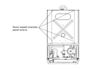
4. In order to gain access to the chamber of combustion – remove all the screws connecting the sealed chamber panel (should be 4). Move panel to the side, pay attention not to scratch, break the seal. Look at the picture below
Attention: When replacing the panel, ensure the seal is intact and that the panel has been located correctly, especially on the sides.
5. In order to get access to all components of the control panel – Remove the all screws connecting the rear cover (should be 5) and slowly raise the cover. While replacing the cover, pay attention to secure all existing wiring. Secure with five screws – do not over-tighten.
6. Re-assemble in reverse order
Draining the boiler
Replacement of most of the parts will require draining the boiler. To properly drain the boiler follow steps below
1. Ensure the electrical supply is isolated and the gas supply is off. Allow the boiler to cool.
2. For Heating circuit -close return valves and flow of the central heating as shown on the picture below.Connect a suitable pipe to the drain point and route it to a suitable container. Open the drain point.
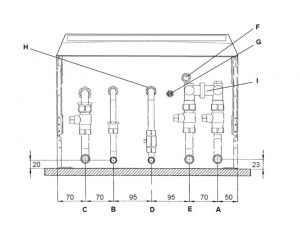
A- 22 mm heating flow
B- 15 mm water outlet-hot
C- 22 mm inlet- gas
D- 15 mm water mains inlet- cold
E- 22 mm return heating
F- 15 mm valve of pressure relief
G- drain point- heating
H- water inlet filter-cold
I-by-pass
3. For Hot water circuit- close the mains water inlet valve as shown on the picture obove. Open any hot tap below the level of the boiler to allow as much draining as possible.Attention: small amount of water will remain in the components and care must be taken when removing them.
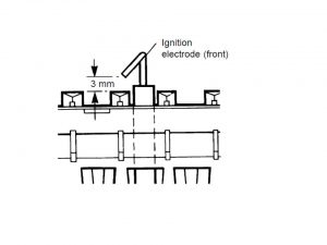
Ignition electrode replacement
1. Isolate the appliance
2. Gain General Access. Gain access to the combustion chamber
3. Disconnect the lead from the electrode
4. Disconnect the lead from the PCB as described on the picture below. Note all positions
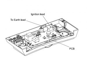
5. Put the new lead the way it smoothly passes through the locations in the panel control and grommets in the base of the combustion chamber.
6. Re-assemble in reverse order.
General electrodes replacement
1. Isolate the appliance
2. Gain General Access. Gain access to the combustion chamber
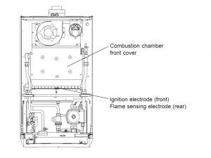
3. Remove all the screws (should be 4) connecting the cover of the combustion chamber and put it aside
4. Disconnect the leads from the electrodes. Remove the grommet in the bottom of the chamber, disconnect the flamesensing electrode in-line connector and withdraw the lead
5. Take out the main burner from the body of the boiler. Pay attention not to scratch or damabe insulation panels on the sides
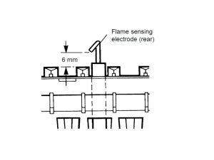
6. (Rear) flame sensing electrode -unscrew all the screws connecting flame sensing electrode and take electrode out. Put the new electrode in, verify if it is correctly positioned and that the gap is correct as shown on the picture below
Attention! Fit the in-line connector to the lead by pushing it into the connector after the burner has been fitted.
7. Ignition electrode (front)-remove all the screws connecting ignition sensing electrode and take electrode out.Put the new electrode in, verify if it is correctly positioned and that the spark gap is correct as shown on the picture below.
8.Re-assemble in reverse order. Replace the burner, ensuring it is located correctly. Re-assemble the front cover of the combustion chamber, making sure it is properly located.
Fan replacement
1. Isolate the appliance
2. Gain General Access. Gain access to the combustion chamber
3. Disconnect the fan wiring
4. Remove the three screws securing the fan to the flue hood. Fit the new fan and re-assemble in reverse order
Attention! Connect the fan wiring, blue to terminal N, brown to terminal L and green/yellow to terminal
5. Re-assemble in reverse order and test the boiler
Air pressure switch replacement
1. Isolate the appliance
2. Gain General Access. Gain access to the combustion chamber
3. The pressure sensing tube should be disconnected
4. Disconnect the wiring and loose all the fixing screw
5. Connect the wiring to the new switch. The polarity of the wires is not important
6. Secure the new switch in position and connect the pressure sensing tube to the connection nearest the front
7. Re-assemble in reverse order.
Overheat thermostat replacement
1. Isolate the appliance
2. Gain General Access. Gain access to the combustion chamber
3. All applicable wiring from the overheat thermostat should be disconnected
4. Remove the spring clip and remove the overheat thermostat from the heat exchanger
5. Fit the new overheat thermostat
6. Re-assemble in reverse order.
Gas valve replacement
1. Isolate the appliance
2. Gain General Access. Gain “behind the casing” access
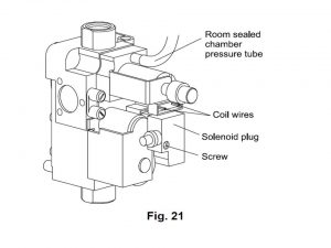
3. Gas valve should be disconnected from pressure tube and all the coil wires
4. Unfix the screw (should be one) as described on the picture below. The plug needs to be disconnected and electrical plug needs to be secured.
5. The gas inlet pipe union should be disconnected from the burner manifold
6. Unfix all the manifold screws (should be two) from below the boiler
7. Gently push the valve into the the rear direction of the boiler. Pay attention not to scratch or damage washer of the sealing manifold. After this lift out the valve assembly
8. Fit the new one
9. Re-assemble in reverse order. Pay attention to lighting the boiler and testing for gas soundness.
Viewing window replacement
1. Isolate the appliance
2. Gain General Access. Gain “behind the casing” access
3. Remove the rubber window frame and remove the damaged glass
4. Re-assemble in reverse order with a new glass. Ensure the rubber frame is located correctly in the front panel.
Internal fuse replacement
1. Isolate the appliance
2. Gain General Access. The fuse is located in the boiler terminal block
3. Move the fuse holder away and take out the fuse. Put in 2 A fast blow fuse, pay attention that the holder snaps into the right position
4.Re-assemble in reverse order, ensure that the terminal block is located correctly on the plastic pins.
PCB replacement
1. Isolate the appliance
2. Gain General Access. Gain “behind the casing” access
3. All PCB wiring connectors should be disconnected
4. Unfix all the screws (should be 5) and gently take out PCB board (it is located in the switch spindles)
5. Re-assemble in reverse order
DHW flow switch replacement
1. Isolate the appliance
2. Gain General Access. Gain “behind the casing” access and drain the circuit
3. Disconnect the wiring from the flow switch
4. Disconnect the two unions and remove the switch.
5. Using a new washer reassemble in reverse order.
Clock replacement (optional part)
1. Isolate the appliance
2. Gain General Access. Gain “behind the casing” access
3. Loose all the screws (should be two) at the rear of the control panel connecting the clock cover
4. Disconnect the wiring from the clock
5. Take out all the remaining clock screws and take the clock out from the control panel.
6. Put the new clock in. Connect the wires following below logic:- terminal 1- blue, terminal 2- brown and , terminals 3 and 4- red wires.
7. Re-assemble in reverse order.
Primary heat exchanger
1. Isolate the appliance
2. Gain General Access. Gain access to the combustion chamber, drain the boiler heating and DHW circuits
3. Remove all the screws (should be 4) connecting the cover of the combustion chamber and put it aside
4. Remove the overheat thermostat and the CH temperature sensor
5. Unscrew all the screws (should be two)connecting the rear baffle plate. Remove the plate.
6. All unions (should be two) connecting return pipes and exchanger should be disconnected
7. Remove the the heat exchanger from the pipes (move it upward), gently take it out of the boiler
8.Remove the pipes from the heat exchanger by releasing the four union connections.
9. New washers should be used when fitting the pipes into the new exchanger heat. Pay attention so that heat exchanger is properly located.
10. Re-assemble following reverse order logic
11. Refill and re-pressure the system.
Combustion chamber insulation replacement
1. Isolate the appliance
2. Gain General Access. Gain access to the combustion chamber
3. Side out the front panel
4. To replace the rear and side panels remove the heat exchanger. Prise out the top of the rearinsulation panel and lift it up and out of the boiler, then slide out the side insulation panels
5. Fit a new panel and re-assemble in reverse order
6. Refill and re-pressure the system
Pressure gauge replacement
1. Isolate the appliance
2. Gain General Access. Gain “behind the casing” access , drain the boiler heating circuit
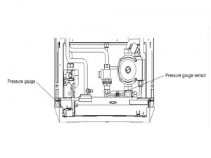
3. Unfix all the screws securing the pressure gauge sensor and take out the sensor as shown on the picture below
4. Depress all the lugs (should be two) located on the pressure gauge. Push lugs out of the control panel
5. Fit the new gauge using a new washer on the manifold connection if necessary
6. Refill and re-pressure the system
7. Re-assemble in reverse order
Temperature sensors replacement
Attention! Both sensors are identical.
1. Isolate the appliance
2. Gain General Access. Gain “behind the casing” access , drain the boiler heating circuit, drain heating circuit for primary sensor or hot water circuit for DHW sensor
3. Primary Sensor – the primary sensor is positioned on the right hand side of the heat exchanger. Unscrew the sensor and disconnect the wiring. When re-assembling (in reverse order) remember to use new sealing washer and new sensor
4. DHW Sensor – you will need to close the cold water mains inlet valve. Next open the lowest tap with hot water to drain the DHW system. Unscrew the sensor and disconnect the wiring. Re-assemble in reverse order with a new sensor, replacing the sealing washer if necessary.
5. Re-assemble in reverse order
Automatic air vent replacement
1. Isolate the appliance
2. Gain General Access. Gain “behind the casing” access , drain the boiler heating circuit
3. Automatic air vent should be disconnected from the pump outlet.
4. Remember to use new ‘O’ ring when placing a new automatic air vent
5. Refill and re-pressure the system
6. Re-assemble in reverse order
Pump replacement
1. Isolate the appliance
2. Gain General Access. Gain “behind the casing” access , drain the boiler heating circuit
3. Unfix all the socket head screws (should be 4) connecting the pump head to the body.
4. Withdraw the head, remove the wiring cove rand disconnect the wiring as described on the picture below
5. Connect the wiring to the new head as follows:-Brown to L, Blue to N, Green/yellow to earthing. Ensure the pump is set to maximum
6. Re-assemble in reverse order
7. Refill and re-pressure the system.
Complete pump replacement
1. Isolate the appliance
2. Gain General Access. Gain “behind the casing” access , perform the boiler heating circuit draining as described in section above. Remove the pump head as described above.
3. The automatic air vent should be disconnected from the pump outlet
4. Disconnect the pump unions and withdraw the pump body
5. Connect the wiring – you can use description from the pump replacement section above. The pump should set to maximum
6. Replace all sealing washers for new ones.
6. Re-assemble in reverse order
7. Refill and re-pressure the system.
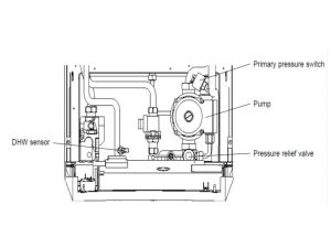
Primary pressure switch replacement
1. Isolate the appliance
2. Gain General Access. Gain “behind the casing” access , drain the boiler heating circuit.
3. Disconnect the wiring from the pressure switch
4. Unscrew the switch from the primary flow pipe
5. Re- assemble in reverse order, replace all washers for the new ones. You don’t need to pay attention to wiring of the new switch, as polarity of those wires won’t be important here.
Pressure relief valve replacement
1. Isolate the appliance
2. Gain General Access. Gain “behind the casing” access , drain the boiler heating circuit
3. Unfix all the screws (should be four) connecting the bottom tray. Remove the tray
4. Outlet fitting of the pressure relief valve should be disconnected.
5. Unscrew the screw connecting the pressure relief valve. Move it aside.
6. Re-assemble in reverse order.
7. Refill and re-pressure the system.
Mains water inlet filter replacement
1. Drain the boiler hot water circuit
2. Remove the four screws securing the bottom tray and removethe tray
3. Withdraw the filter after disconnecting the unions between the inlet valve and boiler
4. Clean or replace
5. Re-assemble in reverse order.
Expansion vessel replacement
Attention! If there is less than 450 mm clearance above the boiler or whenever you use a rear exit flue, it is not possible to replace the vessel. In those cases we advice to use an additional vessel. it can be externally fitted to the boiler by being installed in the return pipe of the central heating. Pay attention so that it is as close to the boiler as possible.
1. Isolate the appliance
2. Gain General Access. Gain “behind the casing” access , drain the boiler heating circuit
3. The pipe should be disconnected from both expansion vessel and the pump inlet manifold
4. Unfix all the screws (should be four) connecting the top of support plate
5. Move the expansion vessel up out of the boiler
6. When replacing the vessel, ensure that the connection is towards the front of the boiler
7. Re-assemble in reverse orderusing new seals as necessary
8. Refill and re-pressure the system